
Monday, December 22, 2008
Wooden kitchen utensils
I made a variety of wooden kitchen utensils to give as holiday gifts this year. These involved a lot of freehand work with a band saw, belt sander, and lathe. The woods are: bloodwood, walnut, maple, mahogany (pie server), and yellow heart. The two curvy-handled utensils on the left are cocktail muddlers. The business-ends are pointing away from the camera, and they are used to crush mint leaves, lime wedges, berries, etc, for cocktails.
Sunday, September 21, 2008
Determining the proper angles to cut pyramid faces
I have built a few projects that involved the construction of a hollow pyramid by assembling triangular faces. As the construction progressed, I quickly realized that the proper miter and bevel angles of each pyramid face are not trivial. ie They are not 45*, 22.5*, 60*, or any other common construction number. The reason is that the faces of the pyramid meet each other in a compound angle, thus making it difficult or impossible to cut the pieces without first calculating the miter and bevel using geometry.
 I made this diagram in Google SketchUp with the dim_angle.rb plugin (http://www.crai.archi.fr/RubyLibraryDepot/Ruby/em_geo_page.htm) . The angles are as follows:
VA = Vertex angle
SA = Slope angle
HA = Hip angle
DA = Dihedral angle (measured in a plane that is orthogonal to the pyramid's sloping edge)
MGA = Miter gauge angle
When building pyramids, the VA and SA are inputs to the following equations. HA is an intermediate step, and the MGA and DA are outputs. These two output angles indicate how the miter and bevel adjustments must be set on the saw to cut the pyramid faces.
For a pyramid with a square base, the VA is 45*. The SA is chosen by the designer to give the pyramid a desired aspect ratio. High SA values, would make the pyramid very tall relative to the base. For this example, let's choose 60*. The first calculation is for MGA:
VA= 45
SA = 60
MGA = arctan(tan(VA)/cos(SA))
MGA = arctan(tan(45)/cos(60)) = 63.43 (not a "common" angle at all!)
Now, the HA is not really useful for setting the saw, but makes the final equation easier to manage.
HA = arctan(sin(SA)*tan(MGA)*cos(VA))
HA = arctan(sin(60)*tan(63.43)*cos(45)) = 50.77
DA = 2(90-(arctan(cot(VA)*tan(HA)*cos(HA)))
DA = 2(90-(arctan(cot(45)*tan(50.77)*cos(50.77) = 104.48
Depending how your saw measures bevel cuts, the proper bevel angle setting is given by just this part of the equation:
arctan(cot(VA)*tan(HA)*cos(HA))
arctan(cot(45)*tan(50.77)*cos(50.77) = 37.76
So, set your saw's miter gauge to the MGA (63.43) and the bevel to 37.76, and cut away. I'm sure you math guys that really loved the "fun" trig identities will have a more compact form for these equations, so feel free to post them.
Tuesday, September 16, 2008
Attaching copper wires to flat plastic ribbon cables
I am going to leave this post published, but I do not recommend this method anymore. The connection is just too fragile. I'll post a better method later.
Many modern electronic device use flat plastic ribbon cables to connect one circuit board to another. These cables are constructed by applying conductive polymer traces to a plastic backing. They cannot be soldered, and are usually connected to the circuit board with a special connector that uses spring pressure to create an electrical contact. If the connector cannot be removed from the board or bought from a supplier, the following technique can be used to attached wires to the ribbon.
First, tape the ribbon cable securely to a work surface (paper-covered tabletop). Then, strip the ends of some small-gauge solid copper wires (I like to use wire-wrap wires). Tape each wire in place, so that the wire is securely positioned over a trace on the ribbon
Mix up a batch of silver, conductive epoxy. This stuff is pretty expensive, but I'm always surprised how little I use for each project, so the supply of it lasts a long time. Load the well-mixed epoxy into a syringe, and use a luer-lock blunt needle tip. The diameter will depend on the pitch of your ribbon cable, but I would say .020" is a good start. The luer-lock tip is important since the syringe needs to be squeezed quite hard to get the viscous epoxy out. Just imagine that needle tip suddenly coming loose, and the syringe squirting epoxy all over!
 Most conductive epoxies have a pot life of about 5 or 10 minutes (depending on ambient temperature). All epoxy must be applied before before the pot life ends, or it will not stick well even though it seems like it might be okay when it is applied. Once the epoxy is applied, I usually use an oven to accelerate the curing. I did not in this case because I was afraid of melting the plastic ribbon cable. Instead, I waited overnight to make sure the epoxy had set.
 Finally, I use a hot glue gun to completely cover the wiring and epoxy joints. This provides a surprising amount of strength, and allows the part to be hanlded carefully without any other mechanical support.
Many modern electronic device use flat plastic ribbon cables to connect one circuit board to another. These cables are constructed by applying conductive polymer traces to a plastic backing. They cannot be soldered, and are usually connected to the circuit board with a special connector that uses spring pressure to create an electrical contact. If the connector cannot be removed from the board or bought from a supplier, the following technique can be used to attached wires to the ribbon.
First, tape the ribbon cable securely to a work surface (paper-covered tabletop). Then, strip the ends of some small-gauge solid copper wires (I like to use wire-wrap wires). Tape each wire in place, so that the wire is securely positioned over a trace on the ribbon

Mix up a batch of silver, conductive epoxy. This stuff is pretty expensive, but I'm always surprised how little I use for each project, so the supply of it lasts a long time. Load the well-mixed epoxy into a syringe, and use a luer-lock blunt needle tip. The diameter will depend on the pitch of your ribbon cable, but I would say .020" is a good start. The luer-lock tip is important since the syringe needs to be squeezed quite hard to get the viscous epoxy out. Just imagine that needle tip suddenly coming loose, and the syringe squirting epoxy all over!
 Most conductive epoxies have a pot life of about 5 or 10 minutes (depending on ambient temperature). All epoxy must be applied before before the pot life ends, or it will not stick well even though it seems like it might be okay when it is applied. Once the epoxy is applied, I usually use an oven to accelerate the curing. I did not in this case because I was afraid of melting the plastic ribbon cable. Instead, I waited overnight to make sure the epoxy had set.
 Finally, I use a hot glue gun to completely cover the wiring and epoxy joints. This provides a surprising amount of strength, and allows the part to be hanlded carefully without any other mechanical support.
Wednesday, September 10, 2008
Metal inlay technique using solder
Here is a technique that I developed to make a metal inlay with solder. I used soft lead solder for this project because it's easy to melt, and I am currently out of silver solder. I imagine the results will be slightly better with silver, since it is harder and will have a better shine.
I attached a piece of .030" thick brass sheet to a thick acrylic spoilboard with double-stick tape (Permacel). Using a 3/64" stub end mill, I CNC cut lettering. I started this cut with WD-40; however, the chip buildup was so large, I switched to water-based flood coolant to get the chips out of there. Cutting specs are: 4000 RPM, about 2.5 inches per minute, .020 depth of cut, 2-flute.

Some edges turned out very clean. For unknown reasons, other edges had a big lousy burr where the cutter pushed metal out of its path (instead of cutting it).
I used a MAPP gas torch to heat small sections of the brass and applied solder after fluxing the piece with acid paste.
I sanded the piece starting with 60 grit (just until I hit the brass), then worked up through each grit until I was using 600 with water. Yes, I use water with the orbital sander, it actually works pretty well! I reattached the piece to the spoilboard with more tape. This makes sanding much easier.
I made a custom polishing tip from aluminum, and a foam-padded piece of felt that was intended to be placed on the ends of table legs. First I used rubbing compound with the custom tip, then white rouge with a loose cotton wheel. I learned that using brown rouge on a spiral-sewn wheel was too aggressive on the soft solder. It preferentially chewed away the solder, leaving the piece uneven and not attractive. I developed the custom tip to distribute the polishing force as much as possible.

The biggest problem is the voids in the solder. I think these are bubbles caused by boiling flux or impurities while the solder is molten. They might also just be low spots where I did not apply enough solder. Oh well, I think it turned out pretty nice. I have also done this technique with acrylic and epoxy instead of brass and solder.


I attached a piece of .030" thick brass sheet to a thick acrylic spoilboard with double-stick tape (Permacel). Using a 3/64" stub end mill, I CNC cut lettering. I started this cut with WD-40; however, the chip buildup was so large, I switched to water-based flood coolant to get the chips out of there. Cutting specs are: 4000 RPM, about 2.5 inches per minute, .020 depth of cut, 2-flute.

Some edges turned out very clean. For unknown reasons, other edges had a big lousy burr where the cutter pushed metal out of its path (instead of cutting it).

I used a MAPP gas torch to heat small sections of the brass and applied solder after fluxing the piece with acid paste.

I sanded the piece starting with 60 grit (just until I hit the brass), then worked up through each grit until I was using 600 with water. Yes, I use water with the orbital sander, it actually works pretty well! I reattached the piece to the spoilboard with more tape. This makes sanding much easier.

I made a custom polishing tip from aluminum, and a foam-padded piece of felt that was intended to be placed on the ends of table legs. First I used rubbing compound with the custom tip, then white rouge with a loose cotton wheel. I learned that using brown rouge on a spiral-sewn wheel was too aggressive on the soft solder. It preferentially chewed away the solder, leaving the piece uneven and not attractive. I developed the custom tip to distribute the polishing force as much as possible.

The biggest problem is the voids in the solder. I think these are bubbles caused by boiling flux or impurities while the solder is molten. They might also just be low spots where I did not apply enough solder. Oh well, I think it turned out pretty nice. I have also done this technique with acrylic and epoxy instead of brass and solder.


Monday, September 8, 2008
MIlling tiny parts from thin brass sheet
I recently completed a project that required me to replace a steel part with a brass one for a small game-controller joystick. In the picture below, there are two brass replacement parts mounted on a small circuit board with the original steel part on the right. The part itself started life as a flat piece of metal that was bent on four axes to produce a 5-sided cube (the bottom face of the cube is open and fits into a white plastic base).

Here are is the original steel part and its brass replacement, which I machined from sheet stock. The stock is about .025" thick, which is just slightly thicker than the original steel. I began this project by unfolding the original part, and scanning it with a flatbed image scanner. I cleaned up the image in the GIMP, and converted it into a vectorized image format. Then, I created a toolpath for my CNC mill. This sounds relatively easy, but it took many hours to accomplish the whole series of tasks. I started experimenting with speeds/feeds/lube/depth of cut, etc, etc and I eventually found a winning combination:
Use stub-length micro endmills. I used a .020" dia end mill, which often broke when I breathed on it too hard. Using stub-length end mills helps prevent breakage.
The depth-of -cut should be about half the tool's diameter, so .010", in this case. I used three passes to cut through the .025" thick stock.

The chipload should be the tool diameter divided by 130. So, .020/130 = .00015. My mill is limited to 4500 RPM, so this means, I can only feed the tool at about 1.4 inches per minute (2 flute cutter). In reality, I chose to use an even slower feed rate of about .5 to .75 inches per minute.
Galling the brass was a big problem, and I found that WD-40 with occasional air blasts to clear the chips worked very well. Probably, a mist coolant system would be the best, but I don't have one.
Workholding was accomplished by using double-stick tape to adhere the brass stock to a thick acrylic spoil board.
I also tried making a fixture to hold my Dremel tool to the mill spindle. This would allow me to spin the tiny end mills at 30,000RPM (proper speed). It was a good idea, but the runout in the Dremel tool (.005") caused the .020" end mills to break very often. It just didn't work, so I would advise against using a Dremel for this kind of milling.


Here are is the original steel part and its brass replacement, which I machined from sheet stock. The stock is about .025" thick, which is just slightly thicker than the original steel. I began this project by unfolding the original part, and scanning it with a flatbed image scanner. I cleaned up the image in the GIMP, and converted it into a vectorized image format. Then, I created a toolpath for my CNC mill. This sounds relatively easy, but it took many hours to accomplish the whole series of tasks.
 I started experimenting with speeds/feeds/lube/depth of cut, etc, etc and I eventually found a winning combination:
Use stub-length micro endmills. I used a .020" dia end mill, which often broke when I breathed on it too hard. Using stub-length end mills helps prevent breakage.
The depth-of -cut should be about half the tool's diameter, so .010", in this case. I used three passes to cut through the .025" thick stock.

The chipload should be the tool diameter divided by 130. So, .020/130 = .00015. My mill is limited to 4500 RPM, so this means, I can only feed the tool at about 1.4 inches per minute (2 flute cutter). In reality, I chose to use an even slower feed rate of about .5 to .75 inches per minute.
Galling the brass was a big problem, and I found that WD-40 with occasional air blasts to clear the chips worked very well. Probably, a mist coolant system would be the best, but I don't have one.
Workholding was accomplished by using double-stick tape to adhere the brass stock to a thick acrylic spoil board.
I also tried making a fixture to hold my Dremel tool to the mill spindle. This would allow me to spin the tiny end mills at 30,000RPM (proper speed). It was a good idea, but the runout in the Dremel tool (.005") caused the .020" end mills to break very often. It just didn't work, so I would advise against using a Dremel for this kind of milling.


Monday, August 25, 2008
Making really perfect, optically-clear acrylic joints
There is surprisingly little information on the 'net regarding acrylic joinery. Gluing two pieces of acrylic is a common operation for many hobbyists and craftspeople, but it seems the only forums that deal with acrylic are those that attract custom aquarium builders. Those projects are often very large and use slightly different techniques than what would be used for small projects. I had to search for a long time and still came up with relatively little info, so I would like to share my experiences.
There are a handful of different general methods that can be used two join one acrylic edge to the surface of another piece. I have tried a few, and think that the "pins method" is definitely the easiest and most reliable. In this method, one piece of acrylic is supported on its edge by a series of pins, spaced about 6 inches apart, above the face of another piece of acrylic. The solvent is applied to the gap and allowed to soften the acrylic for about 30 seconds. The pins are then removed, and the top piece is lowered onto the bottom piece. The joint must be supported for a few minutes until it is strong enough to hold the weight of the piece. The result is usually very good, and the operation can be controlled by using pins of different diameters, and letting the solvent soften the pieces for more or less time.
Step 1: The most critical step is edge preparation. The edge of the acrylic must be extremely flat and smooth. My favorite tools to achieve this in order of preference: 1. Jointer 2. Router 3. Table saw with high-quality blade 4. sanding. I would only recommend sanding if you are preparing the face of a box or the end of a large-diameter acrylic tube. Sanding is usually extremely slow, and does not work at all if you are trying to hand-hold a single sheet of acrylic at 90* to the sandpaper. If sanding is necessary, use a large sheet of glass with sandpaper attached to it with double-sided tape. Push the part back and forth over the sandpaper, and move up through the grits. The glass will make sure the surface is as flat as possible. Generally, water is used with grits 320 and higher, and I would say 320 is as fine as the surface needs to be. I would not recommend a power sander because the are hard to control, usually do not cover the whole surface of the part, and tend to overheat the acrylic.

Step 2: Position the parts with a jig or a square. It's important to position the parts so that the bottom piece extends 1/32" to 1/16" past the outer edge of the top piece. This will hold the excess solvent and will make life easier because the excess can be cut away with a router flush-cut bit later.
Step 3: Insert pins between the bottom and top pieces every six inches. Sewing pins are usually too fat. I like to use short pieces of solid copper wire that measure .015" dia. If the pins are too fat, when you remove them there will be a lot of excess solvent that spills out and it will make a mess.


Step 4. Fill the gap with solvent. Use a standard "hypo applicator" or "needle bottle". Squeeze the bottle while it is upright, then tip it upside-down while loosening your grip on the bottle. It will suck in some air, and prevent the solvent from coming out until you want it to.

Step 5. Remove the pins and let the top piece rest on the lower. Do NOT use any force to push the top piece down. As soon as the top piece is positioned correctly, let it sit completely undisturbed for 5 or 10 minutes.
You can handle the piece very carefully after 10 or 20 minutes (depending on the temperature) and continue with other glue joints in the project. Full-strength usually takes 2 to 4 days. The joint will initially look a little 'textured', however the optical clarity will improve over the next 24 hours. Of course, air-bubbles will never go away, so you can decide right away if the joint is not good enough in that respect.

After a lot of experimenting, I found out that the brand of acrylic and the brand of solvent make a HUGE difference in the quality of the joint. Check out this page which shows a grid of comparisons:
http://www.magconcept.com/acrylic/
There are a handful of different general methods that can be used two join one acrylic edge to the surface of another piece. I have tried a few, and think that the "pins method" is definitely the easiest and most reliable. In this method, one piece of acrylic is supported on its edge by a series of pins, spaced about 6 inches apart, above the face of another piece of acrylic. The solvent is applied to the gap and allowed to soften the acrylic for about 30 seconds. The pins are then removed, and the top piece is lowered onto the bottom piece. The joint must be supported for a few minutes until it is strong enough to hold the weight of the piece. The result is usually very good, and the operation can be controlled by using pins of different diameters, and letting the solvent soften the pieces for more or less time.
Step 1: The most critical step is edge preparation. The edge of the acrylic must be extremely flat and smooth. My favorite tools to achieve this in order of preference: 1. Jointer 2. Router 3. Table saw with high-quality blade 4. sanding. I would only recommend sanding if you are preparing the face of a box or the end of a large-diameter acrylic tube. Sanding is usually extremely slow, and does not work at all if you are trying to hand-hold a single sheet of acrylic at 90* to the sandpaper. If sanding is necessary, use a large sheet of glass with sandpaper attached to it with double-sided tape. Push the part back and forth over the sandpaper, and move up through the grits. The glass will make sure the surface is as flat as possible. Generally, water is used with grits 320 and higher, and I would say 320 is as fine as the surface needs to be. I would not recommend a power sander because the are hard to control, usually do not cover the whole surface of the part, and tend to overheat the acrylic.


Step 2: Position the parts with a jig or a square. It's important to position the parts so that the bottom piece extends 1/32" to 1/16" past the outer edge of the top piece. This will hold the excess solvent and will make life easier because the excess can be cut away with a router flush-cut bit later.
Step 3: Insert pins between the bottom and top pieces every six inches. Sewing pins are usually too fat. I like to use short pieces of solid copper wire that measure .015" dia. If the pins are too fat, when you remove them there will be a lot of excess solvent that spills out and it will make a mess.


Step 4. Fill the gap with solvent. Use a standard "hypo applicator" or "needle bottle". Squeeze the bottle while it is upright, then tip it upside-down while loosening your grip on the bottle. It will suck in some air, and prevent the solvent from coming out until you want it to.

Step 5. Remove the pins and let the top piece rest on the lower. Do NOT use any force to push the top piece down. As soon as the top piece is positioned correctly, let it sit completely undisturbed for 5 or 10 minutes.
You can handle the piece very carefully after 10 or 20 minutes (depending on the temperature) and continue with other glue joints in the project. Full-strength usually takes 2 to 4 days. The joint will initially look a little 'textured', however the optical clarity will improve over the next 24 hours. Of course, air-bubbles will never go away, so you can decide right away if the joint is not good enough in that respect.

After a lot of experimenting, I found out that the brand of acrylic and the brand of solvent make a HUGE difference in the quality of the joint. Check out this page which shows a grid of comparisons:
http://www.magconcept.com/acrylic/
Sunday, August 24, 2008
DIY liquid nitrogen generator
Maker Faire 2010
http://www.youtube.com/watch?v=14B8LynojI4


Old blog post:
You can generate liquid nitrogen (LN2) in the comfort of your own home with some parts found on eBay. I have proven that this is possible by purchasing surplus equipment and assembling it as described in this post. I spent over a year searching eBay, so these parts are not really easy to find, but the total bill for the whole system was under $500. The device consumes about 300 to 400 watts of electricity and needs no consumables (just atmospheric air). The LN2 is produced at a net rate of about 1 liter per day. This comes out to 9.6 kWh/liter or $1.15/liter, which is substantially cheaper than having the local welding store fill up a thermos (granted the thermos must be cooled as it is filled, thus requiring more than its capacity of LN2).
The most important part of this system is the cryocooler. This is a device that employs a thermodynamic gas cycle to pump heat through a very high temperature gradient. Many of these devices are self-contained and require only an electrical input to start pumping heat. The crycooler that I used was removed from a surplus RF filter which used the cryogenic temperatures to maintain a superconducting RF filter. http://www.suptech.com/home.htm
The crycooler itself has been fairly well documented:
http://books.google.com/books?id=POLgG5mma6IC&pg=PA75&lpg=PA75&dq=sti+cryocooler&source=web&ots=ZTMqWVv8Pu&sig=HbbSzGgnD3fIFxyKJjxFLuNEa9E&hl=en&sa=X&oi=book_result&resnum=1&ct=result
I converted the cryocooler to be water-cooled on the hot end and attached a heatsink to its cold end. In operation, the cold end with the heatsink is inserted into the top of a large dewar. Eventually, the interior of the dewar gets so cold that the air will condense into a liquid and drip down to the bottom.
The second key part of this system is the nitrogen separation membrane. The is a device that accepts normal air, and produces relatively pure nitrogen. The waste products (mostly H2O, O2 and CO2) are vented into the air. Information regarding these membrane units is easy to find on the internet, but good luck buying one! They are nearly all produced for huge industrial installations, and those manufacturers will not even return phone calls from interested hobbyists. Asses! I spent a LONG time searching eBay, and eventually found a very compact unit, which was perfectly suited for this project. The nitrogen purity is dependent on the mass flow rate through the device. This means the flow must be carefully monitored and controlled. I will make another post that describes some fun stuff to do with LN2.
http://www.youtube.com/watch?v=14B8LynojI4
I have always been intrigued by science demonstrations using liquid nitrogen, and often made trips to a local welding supply store with my stainless steel vacuum flask to purchase liquid nitrogen and satisfy my cryogenic craving at home. After a few fill-ups, I wondered about the possibility of making liquid nitrogen on demand. Some companies have already produced self-contained liquid nitrogen generators that are designed for small laboratories (http://www.elan2.com/). The Elan2 would be ideal for home experimenters, but the cost is over $10,000, so I decided to build a similar device with less total output, lower purity, and at much lower cost. The device that I built cost less than $500 and produces 1 liter of liquid nitrogen per day.
Nearly all large-scale liquid nitrogen is made by compressing, cooling, and expanding air. This process removes heat from the air and can be repeated until the air liquefies. The condensing gasses are then separated using fractional distillation. This process cannot be easily scaled down because it relies on maintaining a complex, large distillation column to separate nitrogen from the other gasses in air. To avoid using a distillation column, one could use a nitrogen separation device to strip out the nitrogen from air at room temperature. Then, the room temperature nitrogen can be liquefied via the standard compression and expansion method. This is likely the process used in the Elan2 generator. However, it still requires the use of a very high pressure compressor and heat exchanger, extensive insulation and many other custom parts.
Another approach to producing small-scale liquid nitrogen is to use a self-contained cryocooler, which is a specialized refrigeration device that is designed to pump heat across a high temperature differential. In many cases, the devices are specifically designed for small-scale use and designed for spot-cooling in electronics. The benefit of using a cryocooler is that the device requires almost no maintenance and can liquefy gasses at atmospheric pressure. A compressor would not even be necessary in a gas liquefier using a cryocooler, but is helpful for removing water from the air and isolating nitrogen from air’s other component gasses. There are a few different basic types of cryocooler, but this article will highlight free-piston Stirling cycle cryocoolers. These devices are built with an internal piston that is driven by an electrical coil – a linear motor. The piston expands a working fluid (usually helium) in the device while a separate displacing piston moves the fluid to the tip. The piston then reverses direction, compressing the fluid as the displacing piston forces the fluid toward a heat-rejection area of the device. This process is repeated so that the working fluid is constantly being expanded at the tip, and compressed at the heat-rejection area. This causes heat to be pumped from the tip to the rejection area. The rejection area is cooled with atmospheric air, or other fluids that exchange heat with the environment.
Stirling cryocoolers are not relatively common devices, but they are used for RF filters that contain superconducting components. Such RF filters with their integrated cryocoolers can be found on eBay for under $300. One particular unit is the Superfilter built by Superconductor Technologies Inc. It contains a cryocooler that is rated at 140 watts of input power, and is extensively documented here (http://books.google.com/books?id=POLgG5mma6IC&pg=PA75).
I purchased the Superfilter on eBay and extracted the cryocooler. In order to test the device, I attached a small heatsink to the cooler’s cold tip, placed the tip into a household vacuum flask, and powered up the unit. After 30 minutes, I took the cryocooler out of the flask, and noticed a small amount of liquid air had collected at the bottom. Inspired by this success, I continued construction of a more complete liquid nitrogen generator. I already owned a 30-liter dewar (large vacuum flask) and fabricated an acrylic plate that would seal the top of the dewar while the cryocooler was also mounted to the plate with its heatsink hanging down into the neck of the flask. I also removed the cryocooler’s finned heatsink on its heat rejection area and replaced it with a liquid-cooling manifold. Liquid cooling lowered the heat rejection area temperature more effectively than forced air cooling, and this ultimately lead to higher system efficiency.
The liquid nitrogen generator has two basic sections, the dewar with cryocooler, and the air processing equipment that creates dry nitrogen from atmospheric air. The dry nitrogen is fed into the dewar at just above atmospheric pressure where the cryocooler chills the nitrogen until it liquefies and drips off the heatsink. Surprisingly, most of project’s time budget was spent designing and building the equipment to produce dry nitrogen from air. There are some companies who make dry nitrogen supply devices, but even small units are meant for much higher throughput than what is needed by this liquid nitrogen generator. Each liter of liquid nitrogen requires about 700 liters of room temperature nitrogen gas. 700 liters per day is only 0.5 l/min, a very modest flow rate. One popular, but unnecessary use for relatively low-purity nitrogen is filling car tires. I tried to purchase such a machine, but the cost and flow rate were much higher than anticipated. Instead, I found a very small nitrogen separation membrane on eBay. It’s original use was unknown. The separation membrane is the actual component inside commercial nitrogen generators that perform gas separation. The membrane is formed into a large bundle of hundreds of 2mm dia tubes. Air is fed under high pressure into one end of the bundle. The tube walls are semi-permeable and allow oxygen, water vapor, and other “fast” gasses to permeate relatively quickly. Nitrogen and slower (larger molecules) gasses do not permeate as quickly, so the concentration of nitrogen is much higher at the exit end of the tubes than it is at the input end. Higher purities of nitrogen can be achieved by restricting the flow rate through the tubes, thus allowing plenty of time for the unwanted gasses to permeate the tube walls and leave the system. The resulting nitrogen will contain trace amounts of argon and even smaller amounts of other noble gasses.
I also built a dessicator from aluminum cylinders filled with silica gel and plumbed this into to the system before the air reaches the separation membrane. These units are available commercially, and the one that I built is not particularly specialized. Separation membranes also exist for removing water, and this would be an improvement over silica gel dessicators, which require the gel to be dehydrated in an oven after it becomes saturated with water.
The liquid nitrogen generator has proved to be a reliable, but fairly slow method to produce small quantities of liquid nitrogen at home. The initial cool-down of the dewar takes about 12-18 hours, after which liquid nitrogen is produced at a net rate of 1 liter per day. The generator uses about 300 to 400 watts of electricity (includes the water chiller, which cycles on and off), so the energy cost for producing one liter of liquid nitrogen is about 8.5 KWh, or $1.10. This is substantially less expensive than having a thermos filled at a local welding supply store.

Here is a system overview.
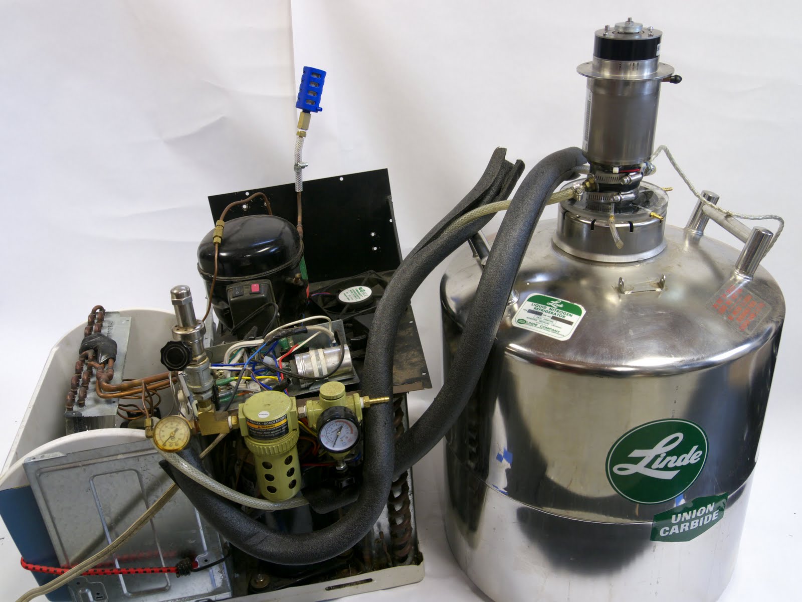
This photo shows liquid nitrogen dewar (on the right) with the cryocooler mounted on top. The device on the left is a window air conditioner that was converted into a water chiller with liquid cooling lines running to the cryocooler. The small compressor on top of the air conditioner pulls air in from the atmosphere and sends it through the nitrogen separation equipment.

The cryocooler with custom heatsink. When the unit is running, the heatsink gets cold enough to condense nitrogen, and the newly formed liquid will drip off the heatsink.

This is the power supply for the cryocooler. The original control board from the STI Superfilter requires 27VDC, so I found a switching power supply from eBay and use that to power the control board.

This is a silica gel desiccator that I built from aluminum. It also contains coalescing filters and carbon filters to remove oil droplets and vapor from the compressed air stream.
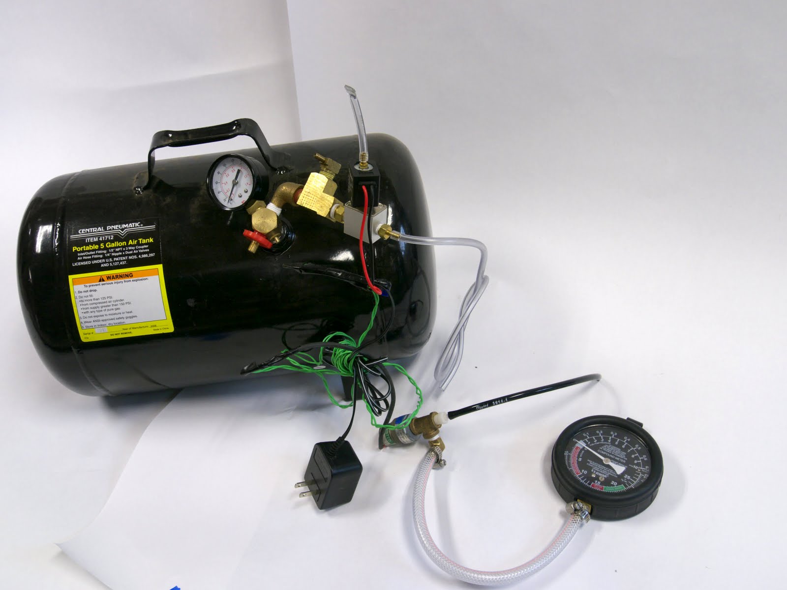
This is the nitrogen storage tank with pressure sensor, valve and gauges.
Liquid nitrogen experiments:
Make Ice Cream
Mix a standard ice cream recipe in a large bowl.
4 cups half-and-half
½ cup heavy cream
¾ cup white sugar
2 teaspoons vanilla extract
pinch of salt
Add liquid nitrogen slowly while stirring the mixture. As the nitrogen boils, it will help froth the ice cream as it freezes the mixture very quickly. The rapid freezing produces small crystals and a fine texture in the ice cream.
Freeze a balloon
Inflate a standard latex balloon with air, then submerge in liquid nitrogen. The balloon will deflate dramatically as the internal gasses contract and even condense. After removing it from the nitrogen, it will reinflate as it warms. This process can be repeated many times.
Perform magnetic levitation on a superconductor
Certain high-temperature superconductors can be used at the boiling point of liquid nitrogen – 77 K. Once the material is cooled, it will exhibit “magnetic mirroring”, so that a permanent magnet can be levitated above the superconductor as its magnetic field is reflected. The best type of magnets for this are small (5mm dia or less, by 2mm long) neodymium-iron-boron magnets.
Make liquid oxygen
A variety of common gasses such as oxygen can be liquefied by passing them through a copper tube submerged in liquid nitrogen. Liquid oxygen can accelerate the combustion of common objects by creating a localized pure-oxygen environment.
Ping-pong ball spinner
Use a needle to puncture a ping-pong ball, then bend the needle to make the hole somewhat tangential to the ball. Repeat this on the other side of the ball with the hole “facing” the opposite direction as the first like a rotary garden sprinkler. Submerge the ball in liquid nitrogen for about 30 seconds, then remove it and place on a large flat surface. The ball will begin spinning as the captive nitrogen boils and streams out through the holes.
Effect on semiconductors
Connect various LEDs to a 9V battery with an appropriate current limiting resistor, eg 1Kohm. Submerge the LED in liquid nitrogen and note its color and brightness. As the semi-conductor cools, the band gap changes, causing a color shift. Some have also suggested the color shift comes from the spacing of the crystal lattice changing due to the very cold temperatures. Different LEDs will show varying degrees of color shift, so try a few from different manufacturers.
Old blog post:
You can generate liquid nitrogen (LN2) in the comfort of your own home with some parts found on eBay. I have proven that this is possible by purchasing surplus equipment and assembling it as described in this post. I spent over a year searching eBay, so these parts are not really easy to find, but the total bill for the whole system was under $500. The device consumes about 300 to 400 watts of electricity and needs no consumables (just atmospheric air). The LN2 is produced at a net rate of about 1 liter per day. This comes out to 9.6 kWh/liter or $1.15/liter, which is substantially cheaper than having the local welding store fill up a thermos (granted the thermos must be cooled as it is filled, thus requiring more than its capacity of LN2).
The most important part of this system is the cryocooler. This is a device that employs a thermodynamic gas cycle to pump heat through a very high temperature gradient. Many of these devices are self-contained and require only an electrical input to start pumping heat. The crycooler that I used was removed from a surplus RF filter which used the cryogenic temperatures to maintain a superconducting RF filter. http://www.suptech.com/home.htm
The crycooler itself has been fairly well documented:
http://books.google.com/books?id=POLgG5mma6IC&pg=PA75&lpg=PA75&dq=sti+cryocooler&source=web&ots=ZTMqWVv8Pu&sig=HbbSzGgnD3fIFxyKJjxFLuNEa9E&hl=en&sa=X&oi=book_result&resnum=1&ct=result
I converted the cryocooler to be water-cooled on the hot end and attached a heatsink to its cold end. In operation, the cold end with the heatsink is inserted into the top of a large dewar. Eventually, the interior of the dewar gets so cold that the air will condense into a liquid and drip down to the bottom.
The second key part of this system is the nitrogen separation membrane. The is a device that accepts normal air, and produces relatively pure nitrogen. The waste products (mostly H2O, O2 and CO2) are vented into the air. Information regarding these membrane units is easy to find on the internet, but good luck buying one! They are nearly all produced for huge industrial installations, and those manufacturers will not even return phone calls from interested hobbyists. Asses! I spent a LONG time searching eBay, and eventually found a very compact unit, which was perfectly suited for this project. The nitrogen purity is dependent on the mass flow rate through the device. This means the flow must be carefully monitored and controlled. I will make another post that describes some fun stuff to do with LN2.
Friday, August 8, 2008
CNC milling glass plates and mirrors
I searched the web for quite a while, but came up empty-handed when looking for information about cutting glass plates with a milling machine. I was fairly certain this would be possible since stained-glass craftspeople routinely use a diamond grinder to quickly remove material from colored glass pieces over 1/8" thick.
I started experimenting and found it quite feasible to use a Computer Numerically Controlled (CNC) milling machine to cut glass plates. I have cut many different thicknesses of glass from .075" thick first-surface mirrors and IR beamsplitters to 1/4" thick frosted glass for art projects.
Here are the critical numbers:
For thin (<.125" thick) glass, I use a .115" diameter diamond burr spinning at 2500 RPM, fed at 1 inch per minute.
For thick (>.125") glass, I use a .25" diameter diamond burr, spinning at 1500 RPM, feed at .5 to 1 inches per minute.
Both situations require flood coolant.
The real trick is to find a suitable clamping method to attach the glass to the milling table. I have settled on edge clamps that exert very little downward force on the glass, but provide a sturdy edge for the glass to butt up against, and also keep the glass from being being pulled upward from the table. Here is a picture of an edge clamp. It was made by passing a piece of thick acrylic over my table saw blade. The resulting dado cut has a peak down the middle, which is actually pretty useful, since I can use a hand file to quickly change the exact height of that peak. I like that the clamp pinches the glass ever so slightly, but exerts the vast majority of clamping force to the waste board, which is also a thick piece of scrap acrylic. Note: Do not use wood for a waste board. It will change shape when it gets wet from the cutting coolant, and will crack the glass!

I used two edge clamps like this to hold a mirror down to a 1/2" thick piece of acrylic waste board

Here is a picture of the finished mirror:

A closeup of the edge:

Thursday, July 24, 2008
Bathroom vanity cabinet
Here are some pictures of a bathroom vanity cabinet that I designed and built for a friend.


Adding pre-amplifier outputs to an Onkyo Receiver
I bought an Onkyo TX-SR505 receiver and really like it. It has a lot of good features, will drive 4 ohm speakers (despite what the manual says), and accepts a variety of signal inputs. However, there is one missing feature that I would really like to have: pre-amplifier outputs. This would allow the use of an external amplifier and additional signal-chain devices (such as a graphic equalizer). I feel strongly that room compensation with a graphic EQ is important, but that is a topic for another post.
I opened the cover on the TX SR505, and eventually found a convenient place to tap into the pre-amp signals. I used some short lengths of shielded cable to connect three newly-added RCA jacks to three points on the main audio board. Note that the cable shield is only connected to the metal receiver case at one end. I think the photos will explain everything better than I could in words, so take a look.


I opened the cover on the TX SR505, and eventually found a convenient place to tap into the pre-amp signals. I used some short lengths of shielded cable to connect three newly-added RCA jacks to three points on the main audio board. Note that the cable shield is only connected to the metal receiver case at one end. I think the photos will explain everything better than I could in words, so take a look.


Wednesday, May 28, 2008
Eliminating sound problems (crackling, popping, stuttering) on a Dell Vostro 1700
I really like the Vostro 1700, but one of the few problematic areas is the sound system. When the computer is completely idle -- no programs running, no downloading, no nothing -- the sound playback from MP3's, WAV's, even CD's has lots of crackling and popping in it. The problem is pretty noticeable since the audio interruptions occur once or twice a minute.
After some web searching, I found that some people have cured similar sound problems on other Dell notebooks by disabling the 802.11a band of the wireless network card. This band is not used for b or g communication, and so probably will not affect wireless communication with modern routers. I disabled the a band (control panel -> system -> device manager -> network card -> options) and it seems to have cured the sound problems completely. I'm guessing the 802.11a frequency domain interfered with the Sigmatel audio chip. Lousy RFI/EMI protection?
After some web searching, I found that some people have cured similar sound problems on other Dell notebooks by disabling the 802.11a band of the wireless network card. This band is not used for b or g communication, and so probably will not affect wireless communication with modern routers. I disabled the a band (control panel -> system -> device manager -> network card -> options) and it seems to have cured the sound problems completely. I'm guessing the 802.11a frequency domain interfered with the Sigmatel audio chip. Lousy RFI/EMI protection?
Friday, May 9, 2008
Enabling "stereo mix" recording on a Vostro 1700 w/ Vista
It seems that either Dell or Dell's soundcard manufacturer decided that customers should no longer have the ability to record audio from the web. In the past, I could use a program like Audacity to record Youtube audio tracks, iTunes tracks, sound effects from games, etc. After buying my new Vostro 1700 laptop from Dell, I noticed the "stereo mix" or "wave out" option is no longer available.
After a few hours of web searching, I found a solution. Download the XP driver for the Vostro's SigmaTel soundcard from here:
http://support.dell.com/support/downloads
The driver number is R171789. Run the .exe and upack the files. Cancel the driver installation, which starts automatically after unpacking. Browse to the unpacked files, and open the properties dialog for setup.exe. Choose it to run in XP SP2 compatibility mode, and to run as administrator. Run setup -- the driver should install without any errors or warnings.
Now, open the control panel, open the "sound" dialog, and select the recording tab. Right-click in the empty space and choose to view both disabled and disconnected devices. There should now be a stereo mix item -- right click on it and enable it.
Subscribe to:
Posts (Atom)